Since the Cuda 14 was released by Jackson Kayak paddlers have expressed that they felt the Smart Track Rudder was too small for the boat. There is now a solution for that.  The SEA-LECT Designs Trucourse Rudder system. The function of the rudder on a kayak is to increase the tracking in windy situations.  As the paddler adjusts the rudder to compensate for the wind keeping the kayak straight will save the paddler energy.

The Jackson Kayak Cuda 14 used in this modification write up had a factory installed Smart Track rudder system at the time of purchase.
It is possible to use the factory installed steering components and line to raise/lower the rudder with a few slight modifications. ThePlasticHull.net  at this time would recommend that you order your kayak from your local Jackson Kayak Dealer without a rudder system installed and that you would do the entire install with SEA-LECT Designs rudder kit following that kits specific manufacturers instructions until and if this rudder system is ever becomes an option from the Jackson Kayak factory. Your local dealer may also have a shop where they may be able to provide the service to install the rudder kit for an additional charge.

This modification will vary from a full kit install being that there was no need to install sliding foot braces steering cables or trim lines plus run all the tubing these cables and lines require to travel through. Merely this was done to see if the system would work on the Cuda 14.


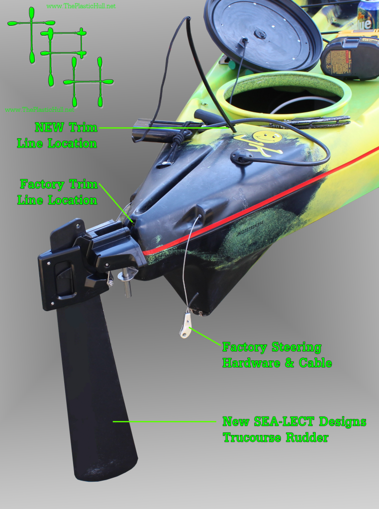
The Diagram to the left shows the location of the factory trim line and then the modified location to work with the SEA-LLECT Designs Rudder.


The new drilled hole is 2 inches from the center line of the edge of the hatch depression to the center line of the drilled hole for the trim line tubing & rope itself. This is only necessary of modifying a Cuda with a factory rudder installed.


Also depicted is the factory installed steering cable and rudder cable. The location of the steering cable does not need to be modified here. Only the connecting hardware needs to be removed. This is done simply by removing the cotter pin pushing the cable inside the mounting bracket and removing the sedge inside. This will free the cable and allow it to be removed.


rudder cabling graphic

The SEA-LECT Designs rudder has an innovative way of  fastening the steering cables. Using an Hex Key tool remove 2 screws each to remove the covers on each side. By loosening up the clamp screw and running the steering cable to the center and then to the rear and tightening down just a little bit.  You will need to center the tracks to the rudder to do this slide the tracks even with the track and this will be your center point. Pull the cable through the rudder till taught but not to move the track off center. Then tighten down the clamp screw.

rudder trim line

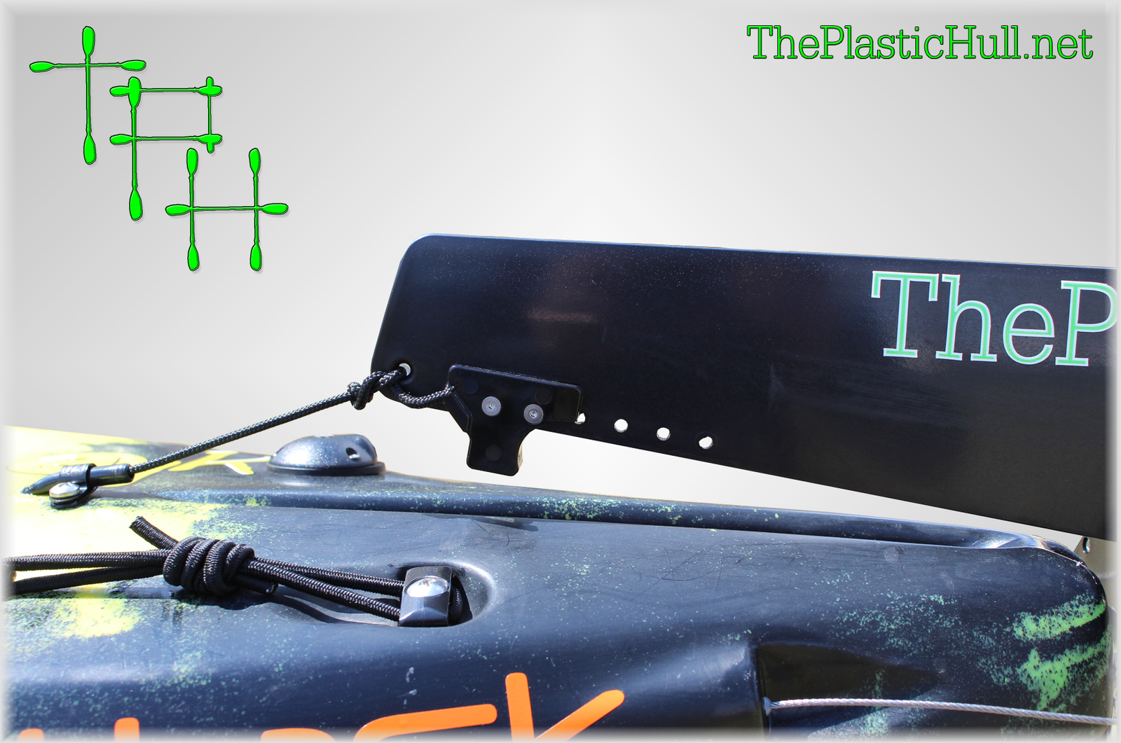
The image above shows the location of the trim line and the new hole drilled along with the 1/4″ wire hanger and stainless steel screw. The existing hole that the trim line penetrated at the stern was just filled with a bead of Lexel. Now to change out the trim line function. Remove the screw at the front of the existing line. If your Cuda has not had a factory installed rudder there should be a plastic screw in this place. Replace this with a screw or if rudder package is installed use the existing screw but add a rigging hook. This will be for the trim line to loop over when the rudder is in the up position. Untie the bungee from the trim line. Now you will pull the trim line to the bow until the rudder is in the up position. This is where you will tie a non slipping loop knot so when looped around the rigging hook the rudder stays in the up position. Now to lower the rudder simply pull the loop off the hook letting it go. The rudder will slide down.

rudder trim

Below is the modified rudder trim control. By releasing the loop from the hook the rudder will go down. By pulling the trim line and hooking the loop the rudder goes up and locks.

trim control

The rudder also has an adjustable depth control. You may want to adjust the height when fishing flats and shallow areas then adjust it down for deeper water. Also for best performance the rudder should not be pulled all of the way up and forward. It could cause the rudder to get stuck in the up position. You may want to tie a knot in the trim line at the stern of the kayak to stop the rudder from being pulled too far.

Rudder Adjust


Disclaimer:
Installing hardware may cause damage and/or void manufacturer warranties.  ThePlasticHull.net its authors or any other source of information on this website is in no way responsible for your actions nor any type issues or damage that may occur.  The information provided on this website is a free reference guide only. The authors of all information, sponsors and the owners of the website that host this information are not liable for any problems or issues that arise from the use of this information. Users of this information hereby acknowledge that all use of this information is done by their own free will, at their own sole risk, understanding that destruction of property, injury, or death could occur.

Took the Big Rig to Round Valley Res on Sunday April 6th for its maiden voyage and to test the Torqeedo motor to see if any tweaks need to be made prior to my publishing of the overall install write up. There is a few things which should be minor adjustments.  Round Valley has crystal clear water so i figured it would be the best for filming there. So through this video together if anyone is interested in checking out how it went!

The music isn’t the best but it was a quick pick. Enjoy!

IMG_1381

Lowrance HDI transducer Kayak Scupper MountCreating a semi-permanent install for multiple kayaks is a challenge. Since most of us fish on a budget two separate fish finder units is not feasible. For about 1/4 the price of a new Lowrance Elite 5 HDI unit you may purchase a new Transducer, Power cable, and the neat Lowrance kayak scupper mount kit. This application is only for sit on top kayaks like the Big Rig with round scupper holes. The mount and this particular transducer as of 2014 other Jackson Kayak Models will not work due to the oval scupper shape and being that the bottom of the supper is simply not wide enough to accept the transducer mounted flush.

Scupper mount

In the photo to the left shown is the un-boxed scupper mount and the transducer and cable. This transducer has been a challenge to mount to other kayaks until the Big Rig with its enlarged hull scupper clearance as it is Raymarine ready.

To install simply using the bolt washers mount to the bottom of the scupper mount as you would the transom mount. Once this is completed pull the plug end of the transducer wire from the bottom of the scupper through towards the deck. IMG_1238Once all of the cable is pulled then insert the threaded plastic into the scupper. The transducer should face bolted end/cable to the bow. Then slide the gray fitting down the threaded shaft and tighten the thumb nut all the way down until snug. Once fit you may cut the shaft and place the Lowrance cap on top. Done!!

This is the best way to install any transducer out there. You get accurate temperature readings and a completely better signal for clarity rather than the shoot thru hull option.


Drill holeI prefer to hide all of my wires and cables within the hull of the kayak. Just less mess less things to snag your hooks on and the best way to protect expensive electronics cables. Due to the 1″ diameter colors on the Lowrance HDI plugs we need to drill a 1″ hole to get these cables inside the hull. Now that’s a huge hole. It took a while to find a part to seal this with for a really clean install. I’m not the type that likes to run cables through hatches. West Marine makes a hull pass through that worked perfectly for this application. I have never seen these used on a kayak before but they are excellent. Low profile watertight and clean!

To start use a 1″ boring drill bit. The hull pass through fitting includes a rubber grommet. I used this as a template placing it exactly where the fitting would be placed. Marked the center with a punch and drilled. See drilled hole to the right. Run sonar plug through and using the thru hull cap press firmly with a screwdriver and screws will self tap. The rubber will push out and this when it is tight. Do not over tighten as the screws will strip out the plastic therefore becoming loose.


Do the same steps for the opposite side but this time with the power wire and the transducer plug through 1 hole. wires & power cable side.lThis one bring the sonar plug through the hole first. Then snake through from the outside the power wire. The power wire will be then run to your battery location. Mine will be in the stern. The white wire in the photo runs back to the stern for the battery box hook up. I will splice that into the power wire for the unit.


Unit installed

Along with the standard molded in center Gear Track on the Big Rig and paired with a Ram Mounts Electronic Mount for Lowrance this is an excellent system! There are now multiple places to position the unit. The option to slide forward or back or mount to the side Gear tracks however is most comfortable.

If you have any questions about this install or anything else please leave me a comment.

Disclaimer:
Installing hardware may cause damage and/or void manufacturer warranties.  ThePlasticHull.net its authors or any other source of information on this website is in no way responsible for your actions nor any type issues or damage that may occur.  The information provided on this website is a free reference guide only. The authors of all information, sponsors and the owners of the website that host this information are not liable for any problems or issues that arise from the use of this information. Users of this information hereby acknowledge that all use of this information is done by their own free will, at their own sole risk, understanding that destruction of property, injury, or death could occur.
Page 7 of 9« First...56789